Installing an Air Handler: Complete Step-by-Step Guide
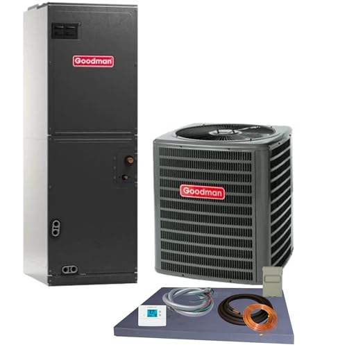
An air handler is the indoor component of a split air conditioning or heat pump system. It houses the blower fan, evaporator coil, and air filtration, and it is responsible for moving conditioned air through your ductwork. While the outdoor condenser handles heat rejection, the air handler is the quiet workhorse that delivers comfort to every room.
Installing an air handler correctly is critical. A poorly installed unit can cause refrigerant leaks, water damage, electrical hazards, reduced efficiency, and premature failure. This guide walks you through the entire process — from planning and placement to wiring, ductwork connection, refrigerant lines, and final testing — so you understand exactly what a proper installation involves and what to expect from a professional crew.
What This Guide Covers
What an Air Handler Does
The air handler is often described as the "indoor half" of a split system. Its main jobs are:
- Circulating air — the blower fan pulls return air from the home, pushes it across the evaporator coil, and distributes conditioned air through the supply ducts.
- Heat exchange — the evaporator coil absorbs heat and moisture from the air in cooling mode; in a heat pump system, it reverses to release heat indoors during heating mode.
- Filtration — the filter slot captures dust, pollen, and debris before air reaches the coil, protecting both the coil and indoor air quality.
- Moisture management — the coil condenses water from the air, which drains through a condensate line and pan.
Understanding the air handler's role helps you appreciate why placement, duct sizing, and refrigerant charge all matter. If you are still comparing system types, review our guide to installing an AC unit and our overview of mini-split air handlers for context on how air handlers fit into different configurations.
Types of Air Handlers
Air handlers come in several configurations, each suited to different installation environments. The table below compares the main categories by tier, best use, and key characteristics.
| Type | Tier | Best For | Key Characteristics |
|---|---|---|---|
| Upflow | Essential tier | Closets, utility rooms, basements | Air flows upward through the unit; most common residential configuration |
| Downflow | Essential tier | Attics, ceilings, tight spaces | Air flows downward into ducts below; common in mobile homes and attic installs |
| Horizontal | Mid-tier | Crawlspaces, low-clearance attics | Air flows horizontally; low profile for height-restricted areas |
| Multi-position | Mid-tier | Flexible retrofit projects | Can be configured as upflow, downflow, or horizontal; versatile for retrofits |
| Variable-speed | Premium tier | Homes needing quiet, even comfort | Blower ramps up and down; better humidity control, quieter operation, higher efficiency |
| Modular / communicating | Luxury tier | Whole-home smart HVAC systems | Communicates with condenser and thermostat; advanced diagnostics and precise control |
If you are installing a ductless setup instead, our mini-split installation guide covers wall-mounted and ceiling cassette configurations, which use a different indoor unit format than a traditional air handler.
Planning and Preparation
Before any equipment is unboxed, a proper installation begins with planning. Skipping this phase is the most common cause of expensive rework.
Verify the Load Calculation
The air handler must be sized to match the home's heating and cooling load, typically determined through a Manual J load calculation. The blower and coil must also match the outdoor condenser's capacity and refrigerant type. Mismatched components cause poor efficiency, short cycling, and premature compressor failure.
Check Electrical Capacity
Most air handlers require a dedicated 240-volt circuit. Confirm your electrical panel has available capacity and that the wire gauge, breaker, and disconnect meet the manufacturer's specifications. If the panel is full or the service is undersized, an electrician may need to upgrade it before installation begins.
Plan the Condensate Route
Condensate must drain by gravity or be pumped to a suitable location. Identify the drain route early — running a condensate line after the unit is set is far more difficult. A secondary drain pan with a float switch is strongly recommended, especially for attic installations.
Gather Tools and Materials
Choosing the Right Location
The location of the air handler affects efficiency, noise, serviceability, and condensate management. Ideal locations include closets, basements, garages, utility rooms, and attics. Consider the following criteria:
- Accessibility — leave at least 24 inches of clearance in front of the unit for filter changes and coil cleaning, and enough room for technicians to service the blower and drain pan.
- Level surface — the unit must sit level to prevent vibration, condensate overflow, and premature bearing wear. Use vibration isolation pads or a properly built platform.
- Duct proximity — placing the air handler near the main trunk reduces duct runs and static pressure losses.
- Moisture protection — avoid locations prone to flooding or standing water. In attics, install a secondary drain pan with a float switch.
- Noise isolation — avoid placing the unit directly above bedrooms or living areas when possible; variable-speed blowers are noticeably quieter in these locations.
- Combustion air — if the air handler shares space with a gas furnace or water heater, ensure adequate combustion air and proper venting.
Step-by-Step Installation Process
The sequence below reflects a standard replacement or new installation. The exact steps vary by configuration, but the overall flow applies to most residential projects.
1 Disconnect Power and Prepare the Site
Turn off the breaker feeding the air handler and the outdoor condenser. Verify power is off with a non-contact voltage tester. Remove the old unit if replacing, disconnect the refrigerant lines (recover refrigerant first per EPA rules), and cap the lines to prevent contamination. Clean the platform and inspect for water damage or rot.
2 Set the Unit and Level It
Position the air handler on the platform or mounting brackets. Use a spirit level to confirm it is level front-to-back and side-to-side. Install vibration isolation pads under the cabinet. If the unit is in an attic or on a ceiling, use appropriate hangers and ensure the structure can support the weight.
3 Connect the Ductwork
Attach the supply plenum to the top or side of the unit, and the return plenum to the return side. Use mastic sealant and foil tape on all seams — duct leakage in an attic or crawlspace can waste a significant portion of the system's capacity. Ensure the return duct is sized to the unit's airflow rating (typically 400 CFM per ton). If your project involves new duct runs, our guides on insulated air ducts and insulated flexible ducts explain the options.
4 Install the Condensate Drain
Connect the primary drain pan outlet to a drain line with a continuous downward slope. Install a P-trap to prevent air from being drawn through the drain. Route the line to a suitable discharge point. Add a secondary drain pan with a float switch, and wire the switch to shut off the system if water accumulates.
5 Connect the Refrigerant Lines
Run the line set between the indoor coil and the outdoor condenser. Keep the lines as short and direct as possible, protect them from physical damage, and insulate the suction line. Braze or flare connections per the manufacturer's instructions. Pressure-test with dry nitrogen, then evacuate the system with a vacuum pump to below 500 microns before releasing refrigerant.
6 Make Electrical Connections
Connect the high-voltage power supply to the unit's disconnect switch, then to the air handler's terminal block. Connect the low-voltage control wiring between the air handler, thermostat, and condenser. Follow the wiring diagram on the unit's access panel. Torque terminals to the manufacturer's specification and verify all connections are tight.
7 Install the Filter and Close Panels
Install a clean filter of the correct size and MERV rating. Replace all access panels and ensure gaskets are intact to prevent air leakage. Confirm the filter is oriented correctly and fully seated.
8 Test and Commission the System
Restore power, set the thermostat to call for cooling, and verify the blower starts. Check airflow at supply registers, measure the temperature split between return and supply air (typically 15–20°F), and confirm the condensate drains properly. Record refrigerant pressures and superheat or subcooling values against the manufacturer's charging chart.
For a broader look at how the indoor unit integrates with the rest of the system, see our guide to installing central AC. If your home has no existing ductwork, review installing central air in a house without ducts before committing to an air handler solution.
Ductwork and Airflow Considerations
An air handler is only as good as the duct system it connects to. Undersized or leaky ducts cause high static pressure, reduced airflow, and comfort complaints even when the equipment is sized correctly.
- Return air sizing — the return duct should be large enough to handle the blower's rated airflow. Undersized returns starve the blower and increase noise.
- Sealing — seal all duct joints, seams, and penetrations with mastic or foil tape. In attics and crawlspaces, duct leakage is a major efficiency loss.
- Insulation — ducts passing through unconditioned spaces must be insulated to prevent condensation and heat gain. Our insulated ductwork guide covers R-values and installation details.
- Static pressure — measure external static pressure after installation. Most residential air handlers are rated for 0.5 in. w.c.; higher readings indicate duct restrictions that should be corrected.
- Balancing — after installation, balance airflow across rooms using damper adjustments so each space receives its design airflow.
If you are connecting the air handler to existing ductwork, our guide to installing central air with existing ductwork covers inspection and adaptation considerations.
Electrical and Refrigerant Connections
Electrical Requirements
Most residential air handlers require a dedicated 240-volt circuit. The breaker and wire gauge must match the unit's nameplate rating — typically a 15- to 30-amp circuit depending on blower size and whether electric heat is included. A local disconnect switch within sight of the unit is required by code in most jurisdictions. Low-voltage control wiring (24V) connects the thermostat, air handler control board, and condenser contactor.
Refrigerant Line Considerations
The line set connects the indoor coil to the outdoor unit. Key points:
- Use the line size specified by the manufacturer — undersized suction lines reduce capacity and can damage the compressor.
- Keep line length and vertical rise within the manufacturer's limits.
- Insulate the suction line fully to prevent condensation and energy loss.
- Pressure-test with nitrogen and evacuate to below 500 microns before charging.
- Charge refrigerant by weight or by superheat/subcooling per the manufacturer's chart — never "top off" by guesswork.
Testing and Commissioning
A thorough commissioning process confirms the installation is safe and performing as designed. Key checks include:
- Electrical safety — verify grounding, tight terminal connections, and correct breaker sizing.
- Airflow verification — measure static pressure and confirm the blower is delivering the rated CFM.
- Temperature split — a 15–20°F difference between return and supply air indicates proper cooling operation.
- Refrigerant charge — check superheat (fixed-orifice systems) or subcooling (TXV systems) against the manufacturer's chart.
- Condensate test — pour water into the drain pan and confirm it flows freely to the discharge point.
- Filter and panel check — confirm the filter is clean and correctly installed, and all panels are sealed.
- Thermostat calibration — verify the thermostat reads accurately and cycles the system correctly.
Document all readings for warranty purposes. A properly commissioned system runs quieter, lasts longer, and delivers the efficiency you paid for.
Common Installation Mistakes
- Mismatched equipment — pairing an air handler with an incompatible condenser causes efficiency loss and premature failure.
- Undersized return duct — restricts airflow, increases noise, and reduces capacity.
- No secondary drain pan in attics — a clogged primary drain can cause significant water damage.
- Poor duct sealing — leakage in unconditioned spaces wastes energy and can introduce contaminants.
- Skipping the vacuum — moisture and air left in the lines cause acid formation and compressor damage.
- Incorrect refrigerant charge — guessing instead of weighing in or checking superheat/subcooling leads to inefficiency and failures.
- Not leveling the unit — causes vibration, noise, and condensate overflow.
- Ignoring static pressure — high static pressure reduces airflow and strains the blower motor.
Frequently Asked Questions
How long does it take to install an air handler?
A straightforward replacement typically takes four to eight hours for an experienced technician. New installations that require ductwork modifications, electrical upgrades, or refrigerant line routing can take one to two days. Attic installations and multi-story homes may take longer due to access and safety considerations.
Can I install an air handler myself?
Air handler installation involves high-voltage electrical connections, refrigerant handling regulated by the EPA, and precise ductwork fitting. These tasks require licensed professionals in most jurisdictions. DIY installation is only reasonable for simple tasks like preparing the space, changing filters, or clearing the condensate drain. The core installation should be left to a licensed HVAC contractor.
Where should an air handler be placed?
Common locations include closets, attics, basements, garages, and utility rooms. The ideal spot provides easy access for maintenance, adequate clearance for airflow, a level surface, and protection from moisture and extreme temperatures. In attics, a secondary drain pan with a float switch is strongly recommended.
What size air handler do I need?
Air handler sizing must match the outdoor condenser and the home's heating and cooling load, typically calculated using Manual J. An undersized unit struggles to distribute air, while an oversized unit causes short cycling and uneven temperatures. The blower's CFM rating should align with the system's tonnage — roughly 400 CFM per ton.
Does an air handler need a separate electrical circuit?
Yes. Most air handlers require a dedicated 240-volt circuit with an appropriately sized breaker and a local disconnect switch. Some smaller units may use 120-volt power, but a dedicated circuit is always recommended. The circuit must match the unit's nameplate rating and local electrical code requirements.
How often should an air handler be serviced?
Annual professional maintenance is recommended — ideally in spring before cooling season. Between service visits, change or clean the filter every one to three months depending on filter type and household conditions. Keep the condensate drain clear and inspect the drain pan for standing water.
Ready to Compare Air Handlers?
Review our recommended models and explore features, configurations, and efficiency ratings side by side.
View Recommended Air Handlers